
I’m assuming that the OVA is deployed with the basic configuration
For this lab, I will only use one NSX Manager appliance for Production you need to use 3.
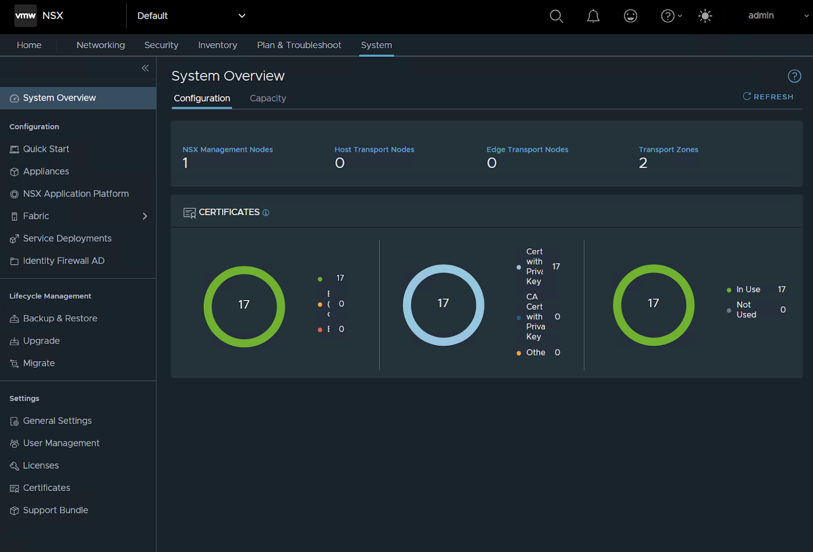
And that you logged on NSX manager
Now that the basic is done the fun starts !!
Create IP pool for the TEP’s
Networking / IP address Pools
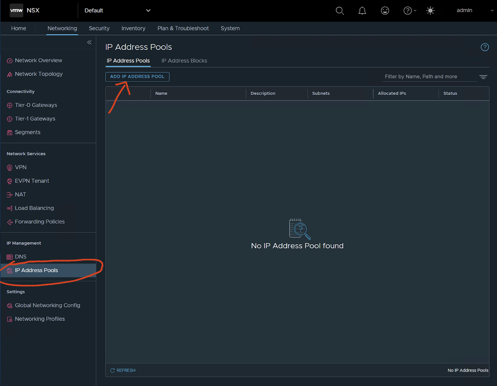
Now let’s create an IP pool for the TEP interfaces, in my case I will use the same range for the TEPS of the hosts and edges.
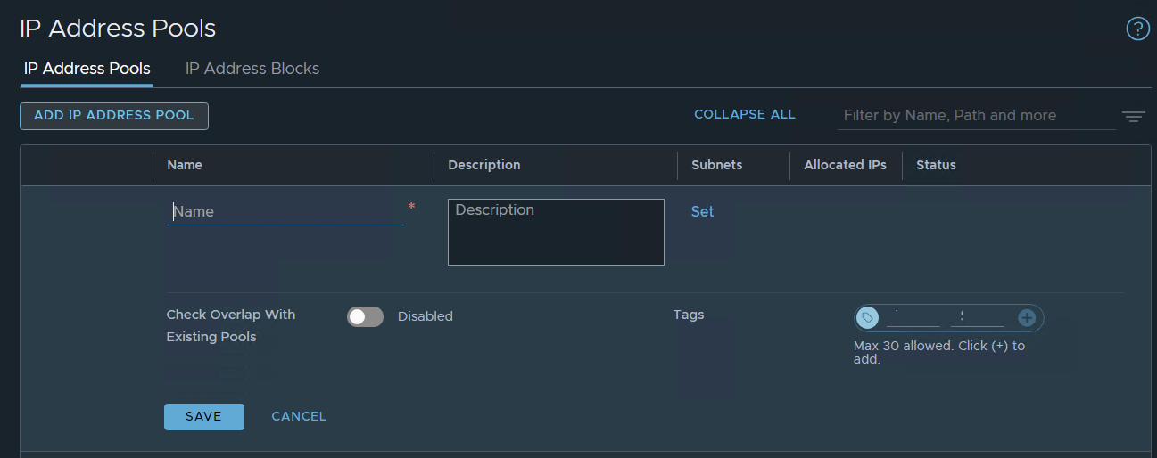
let’s call it a great name !!!
TEP-POOL
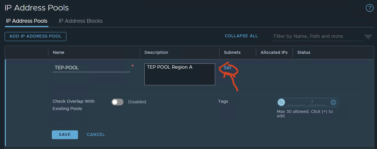
Press set
in my case, I’m going to use IP Ranges but I could use the entire subnet because I will use a different subnet in my other lab for Region B (coming soon).
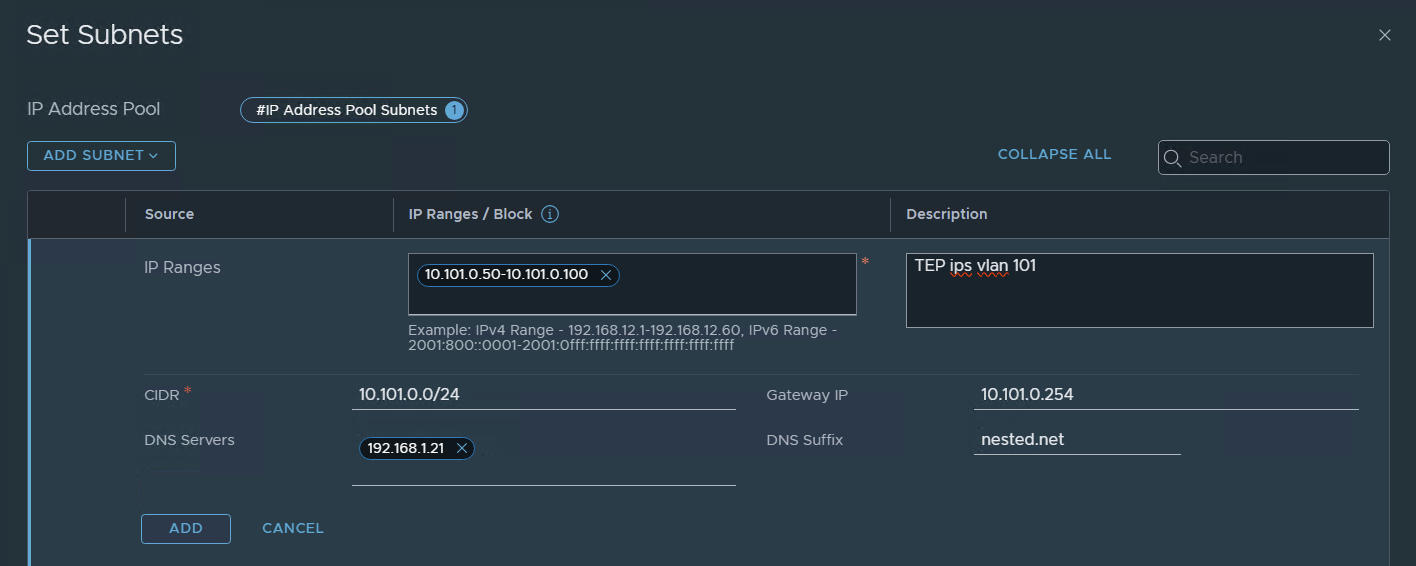
ADD / Apply / Save
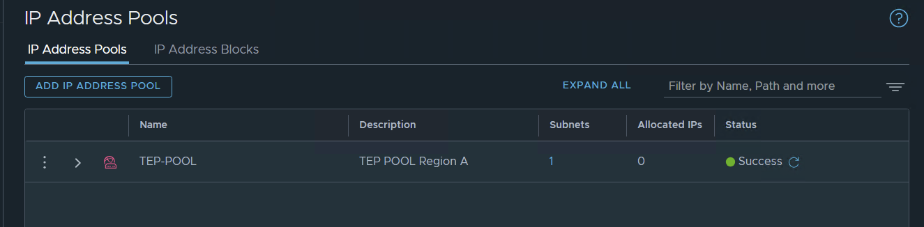
and that’s it.. we now have an IP pool with a range from 10.101.0.50 to 100 for Tunel End Points.
Add a Compute manager (lab vCenter)
System / Fabric – Compute Managers
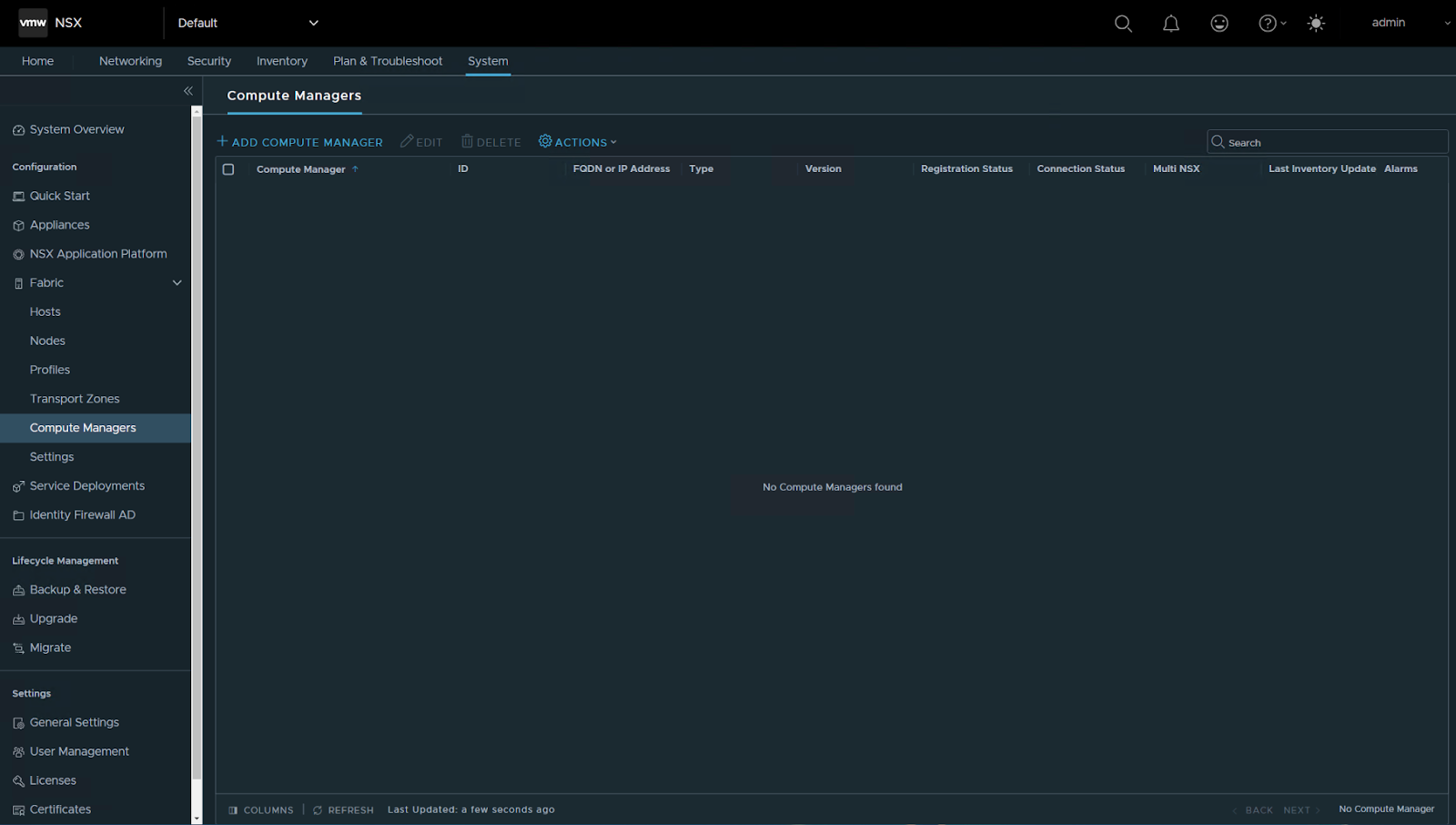
Add compute Manager
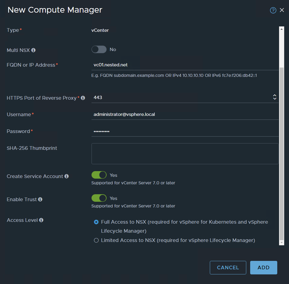
ADD
Accept the certificate
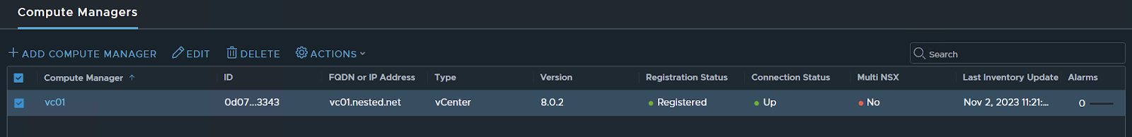
Done
Now Let’s create the uplink profiles for hosts and Edges
System / Fabric – Profiles / Add profile
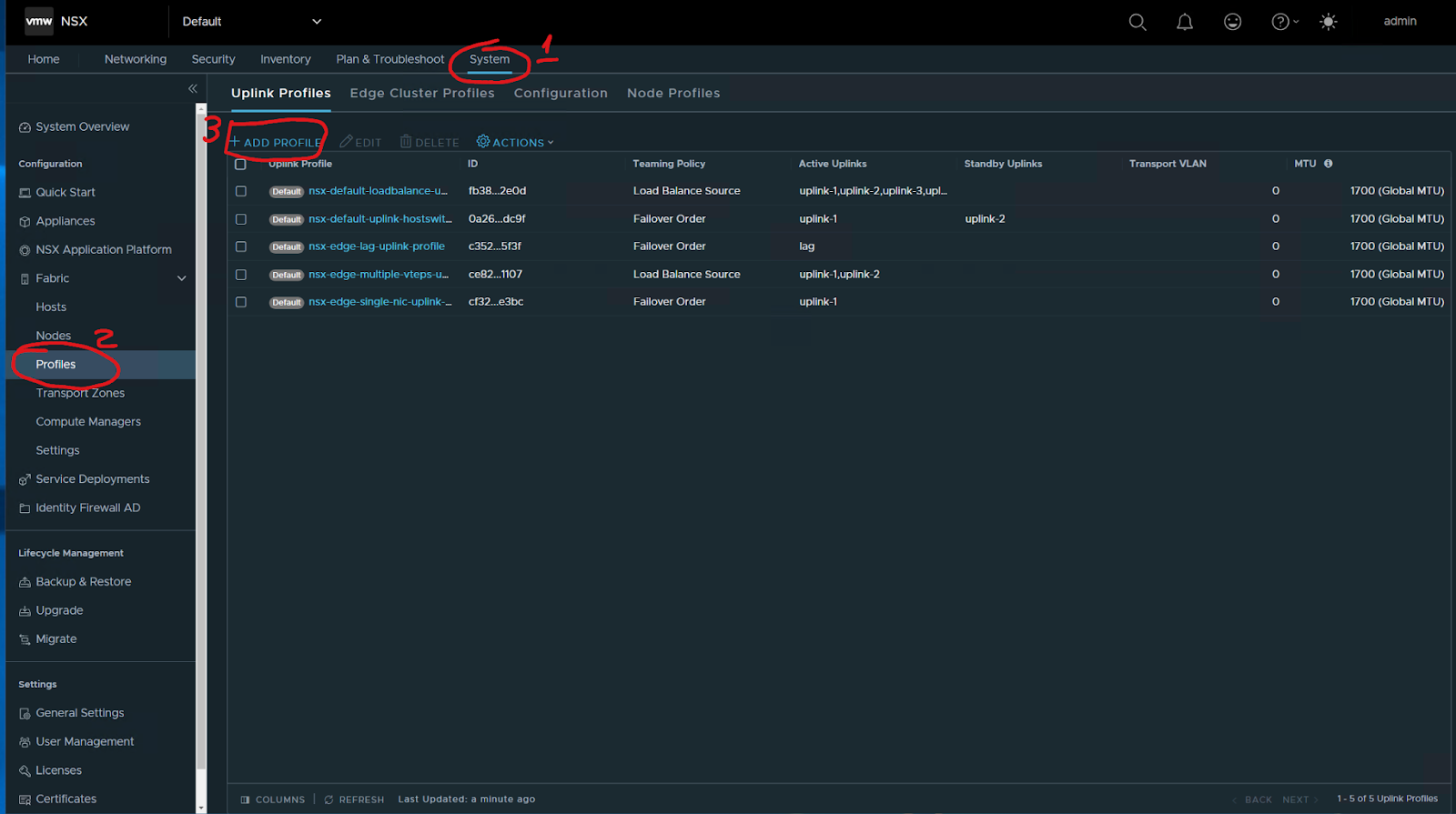
I started to define an uplink profile for hosts
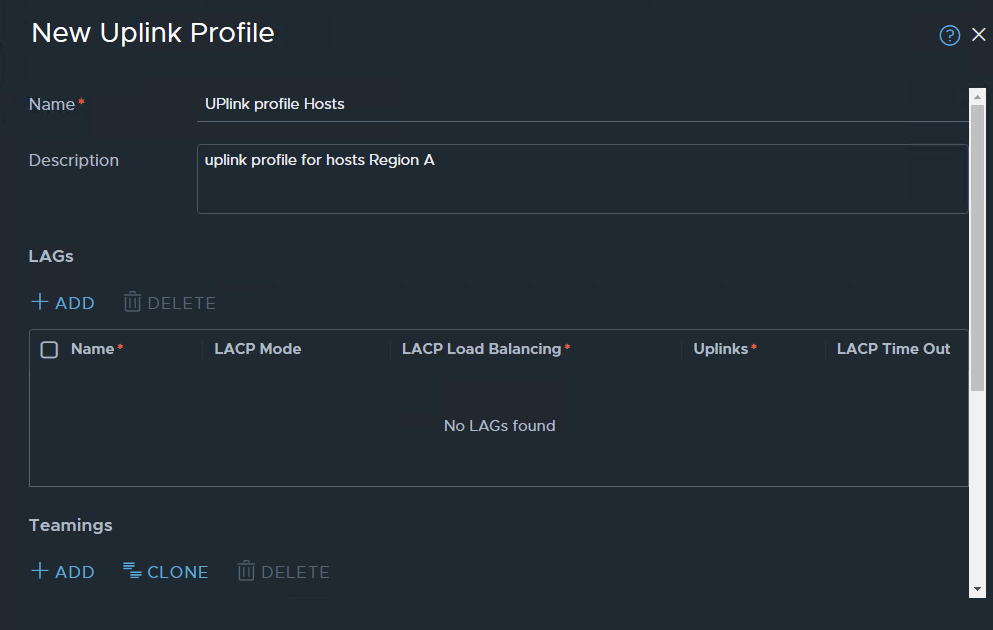
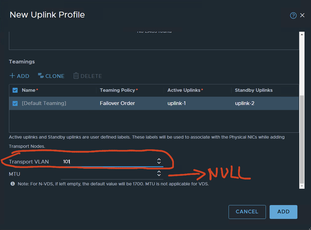
VLAN 101 is configured for TEP traffic, leaving the MTU value Blank. because the VDS-defined MTU will be used.
ADD….
uplink profile for edges:
ADD profile
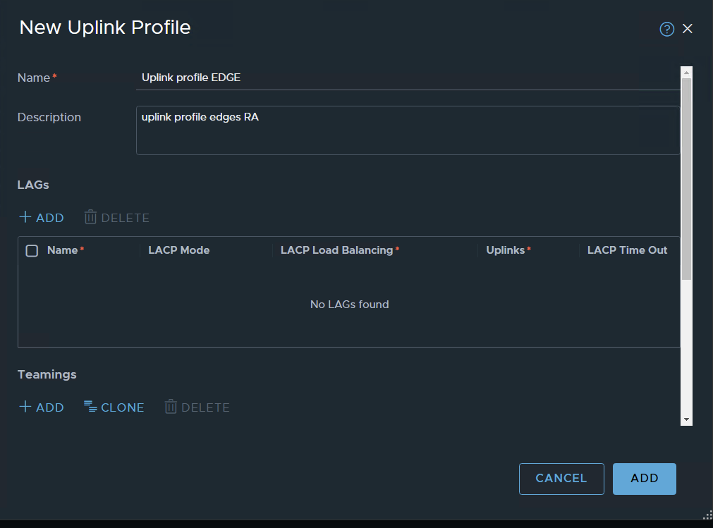
Same as for the host profiles: VLAN 101 for transport, MTU will be defined by VDS
for the edges, I’m using Load Balanced Source
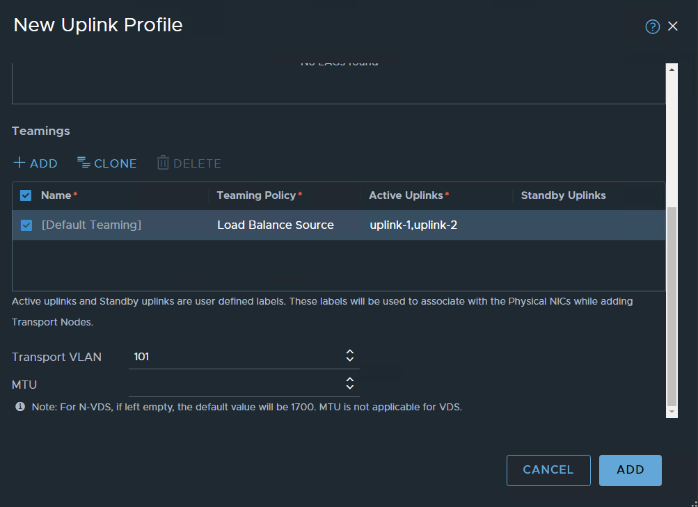
ADD
The two profiles:

Create Transport Zones for Overland and VLAN
System / Fabric – transport zones
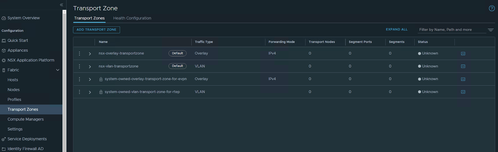
Add Transport Zone
We will create two TZ one for OVERLAY the other for VLAN
Overlay TZ
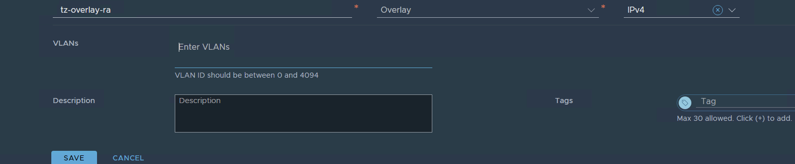
VLAN TZ
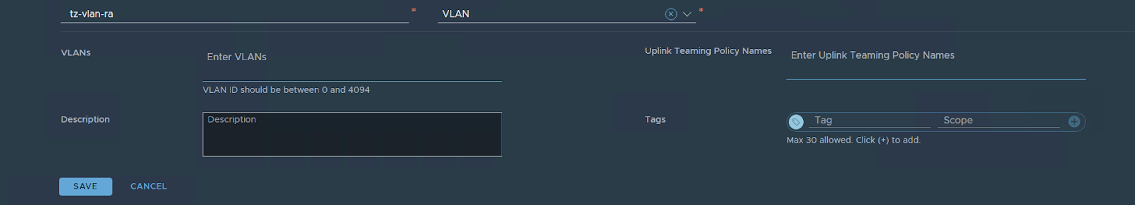
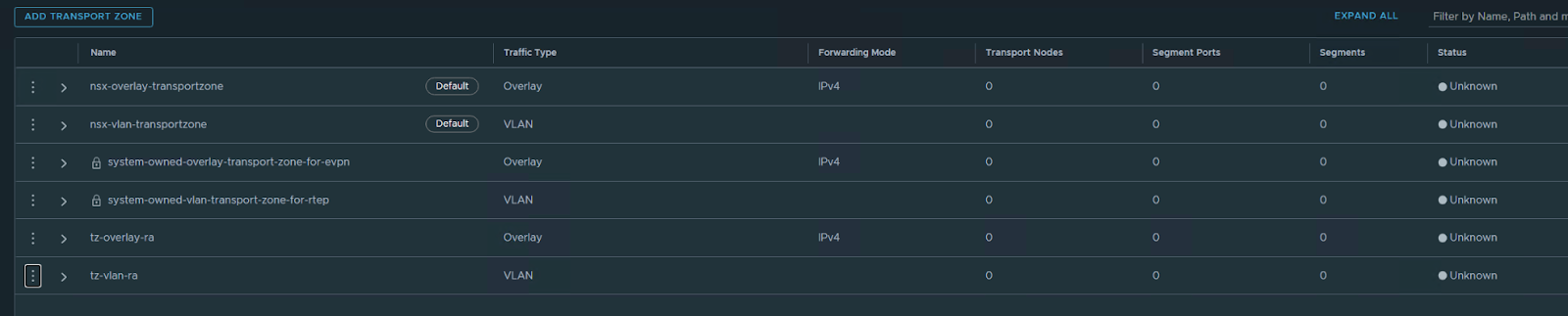
the two transport zones are created
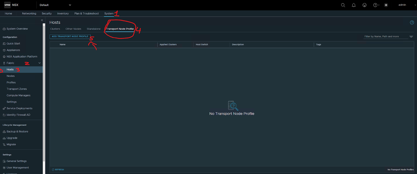
ADD a transport node Profile:
system / Fabric – hosts
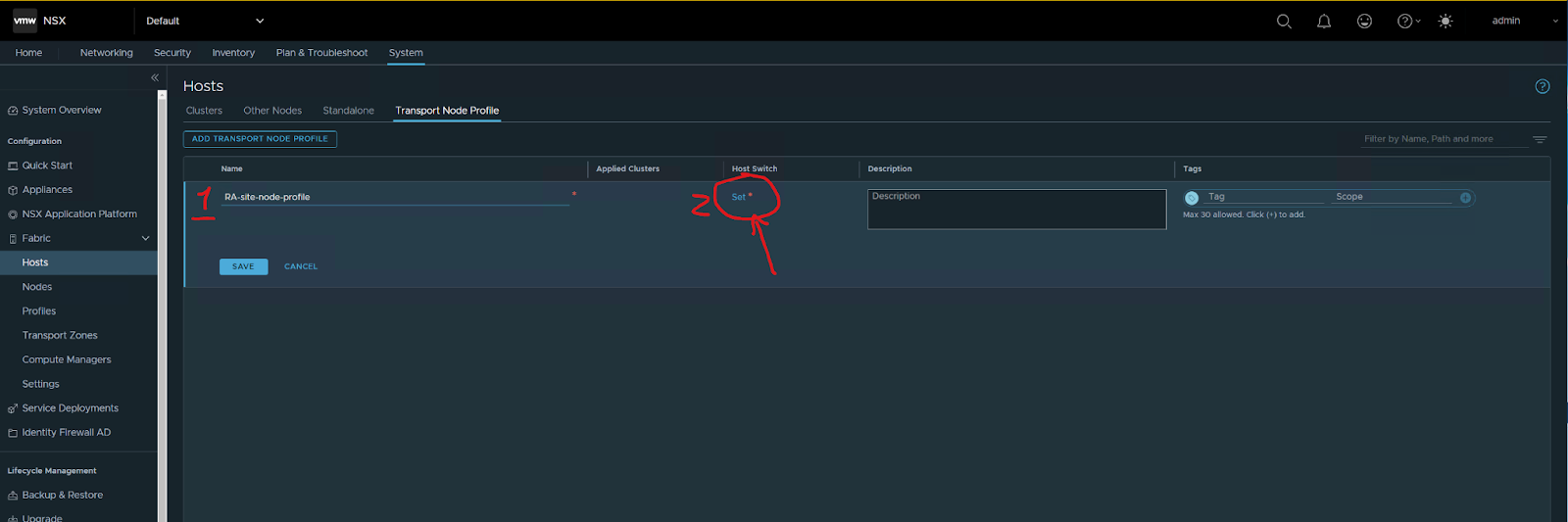
Type the name of the profile then press set
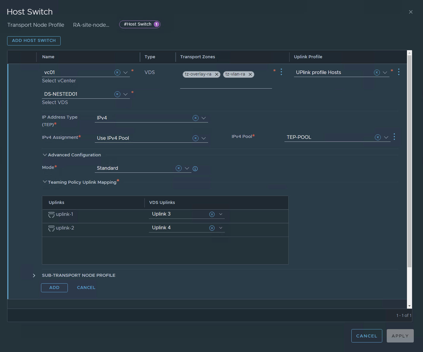
Press add, then apply, then save
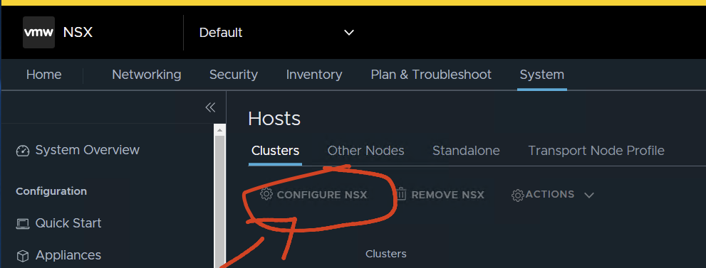
Next, configure hosts:
System / Fabric – hosts/clusters
Select the cluster and then Configure NSX
Just do: configure NSX
Choose the profile
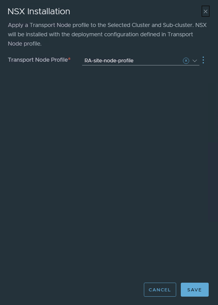
Save
it will start configuring, after some time !!
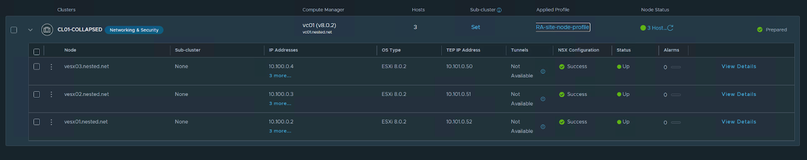
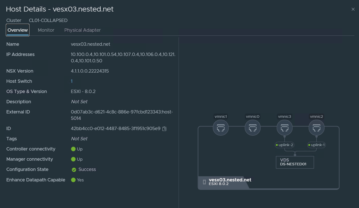
Just looking at the details of one of the Transport Nodes:
Now let’s run some basic but important tests to check the TEPS:
run:
esxcfg-vmknic -l check my VMKernel nics
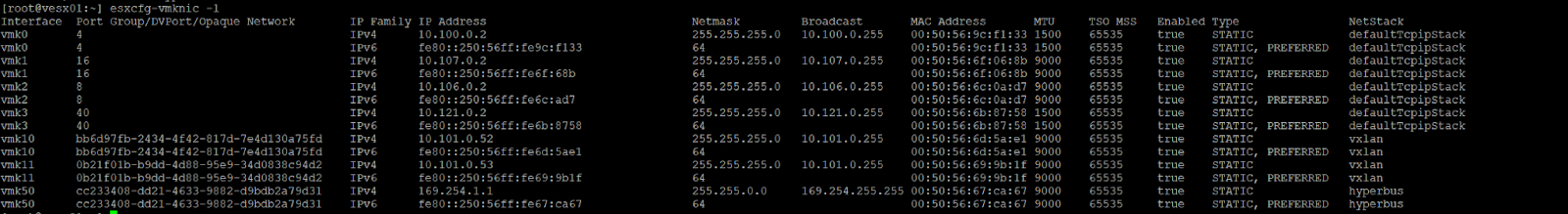
vmk10 is one of the Interfaces of the TEP (in the above case vesx01 has two vmkernel interfaces with one IP on each 10.101.0.52 and 53.
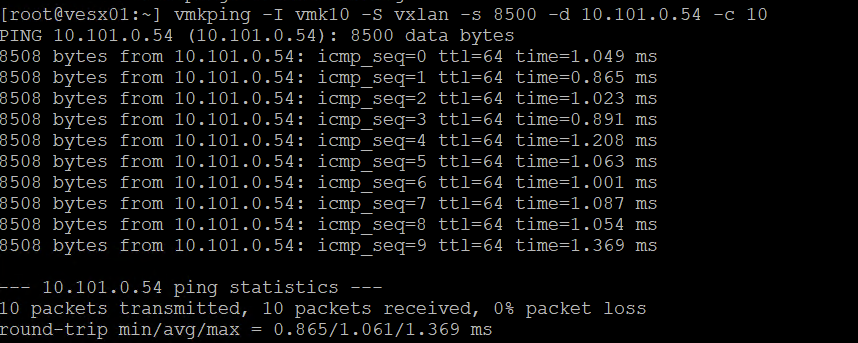
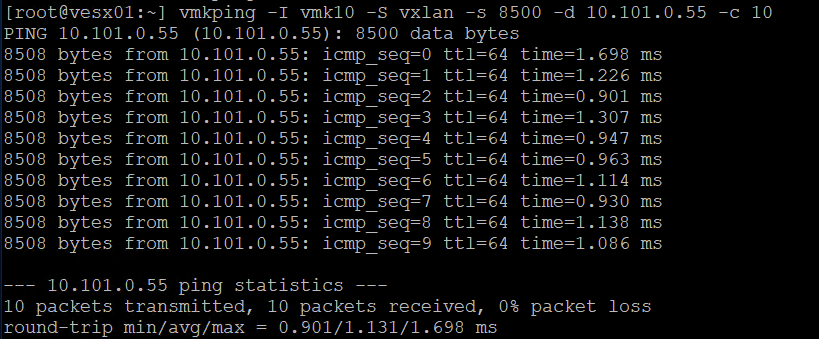
In the two images above I tested ping over the TEP network vesx02 and vesx03
I used this syntax on the command
vmkping -I vmk10 -S vxlan -s 8500 -d 10.101.0.55 -c 10
int VMK netstack size remote tep ping count
Create Trunk VLAN Segment:
To put our Edge TEPs onto VLAN 101, we need to create a VLAN Trunk segment within NSX.
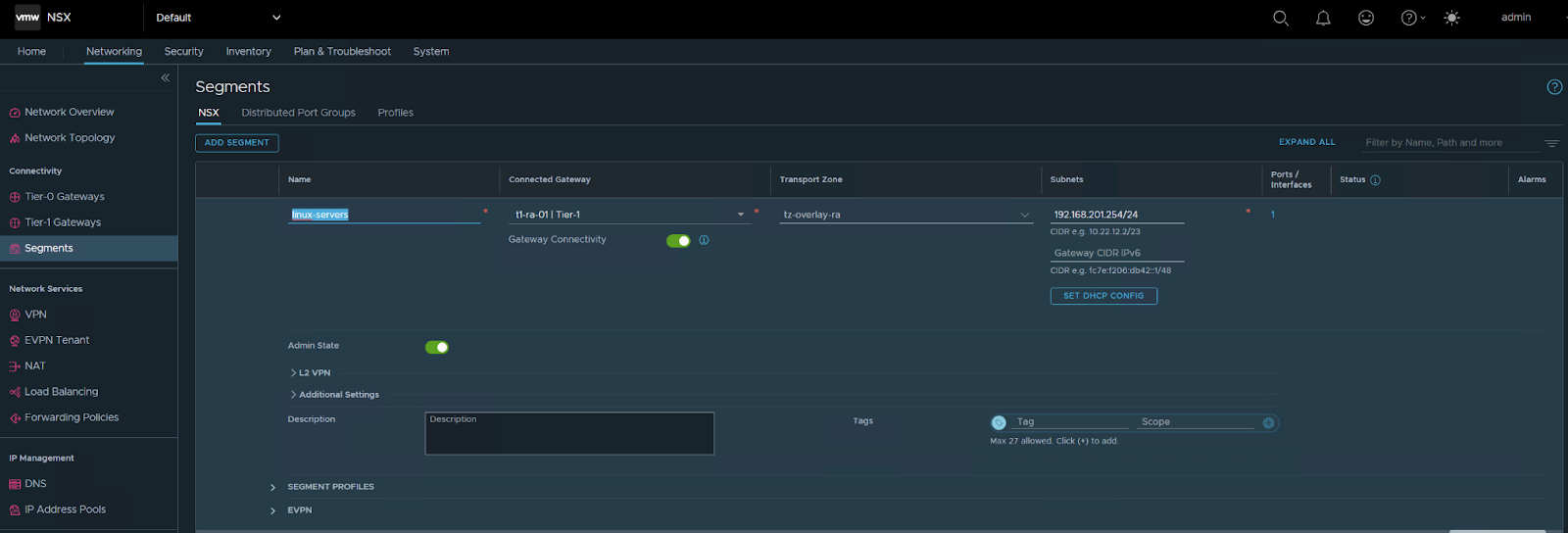
Select Networking / Segments – Add Segment.
Just type the name, and choose the TZ for VLAN that we already defined in the VLAN since it’s a global trunk I typed 0-4094 but you can limit this to the range of VLANS you want to pass in this TRUNK in my case i want to pass all VLANs.
SAVE

choose NO
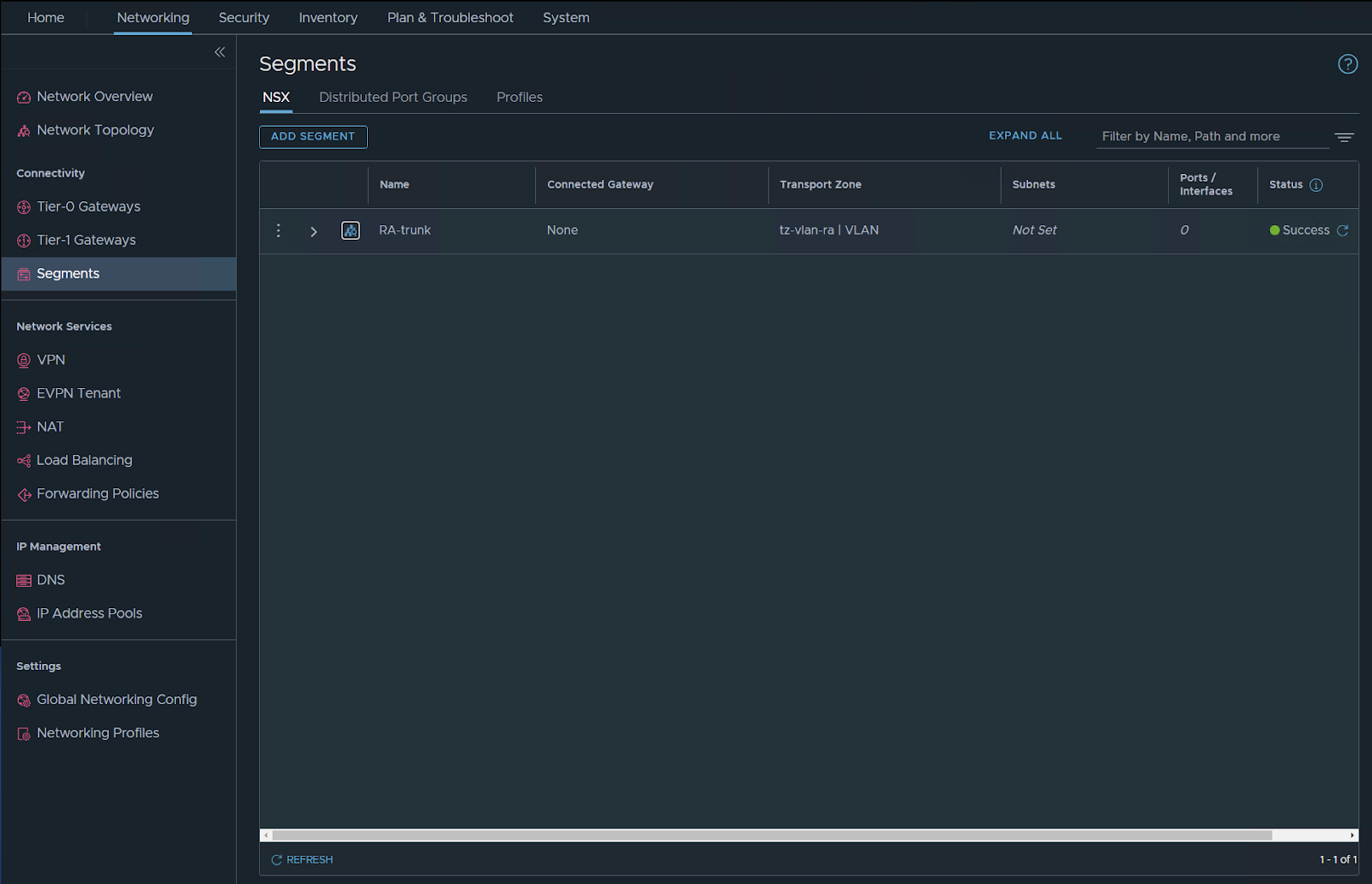
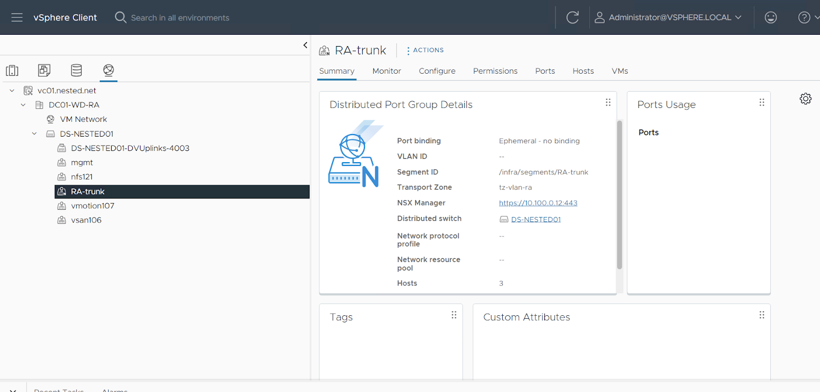
Check the vDS you should have the segment visible there but with N (it’s NSX managed).
Create Region A Edge Node:
The following edge configurations are for lab testing don’t use these sizings in the real world… always check your requirements for edge and use them.
just for LAB, i will use a small deployment
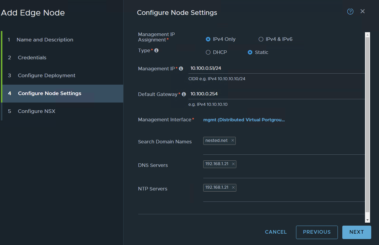
Select System / Fabric / Nodes Edge – Transport Nodes – Add Edge Node.
Name the node en01.nested.net. Set Form Factor to Small
Set CPU Reservation priority to Normal and Memory Reservation to 100 and NEXT
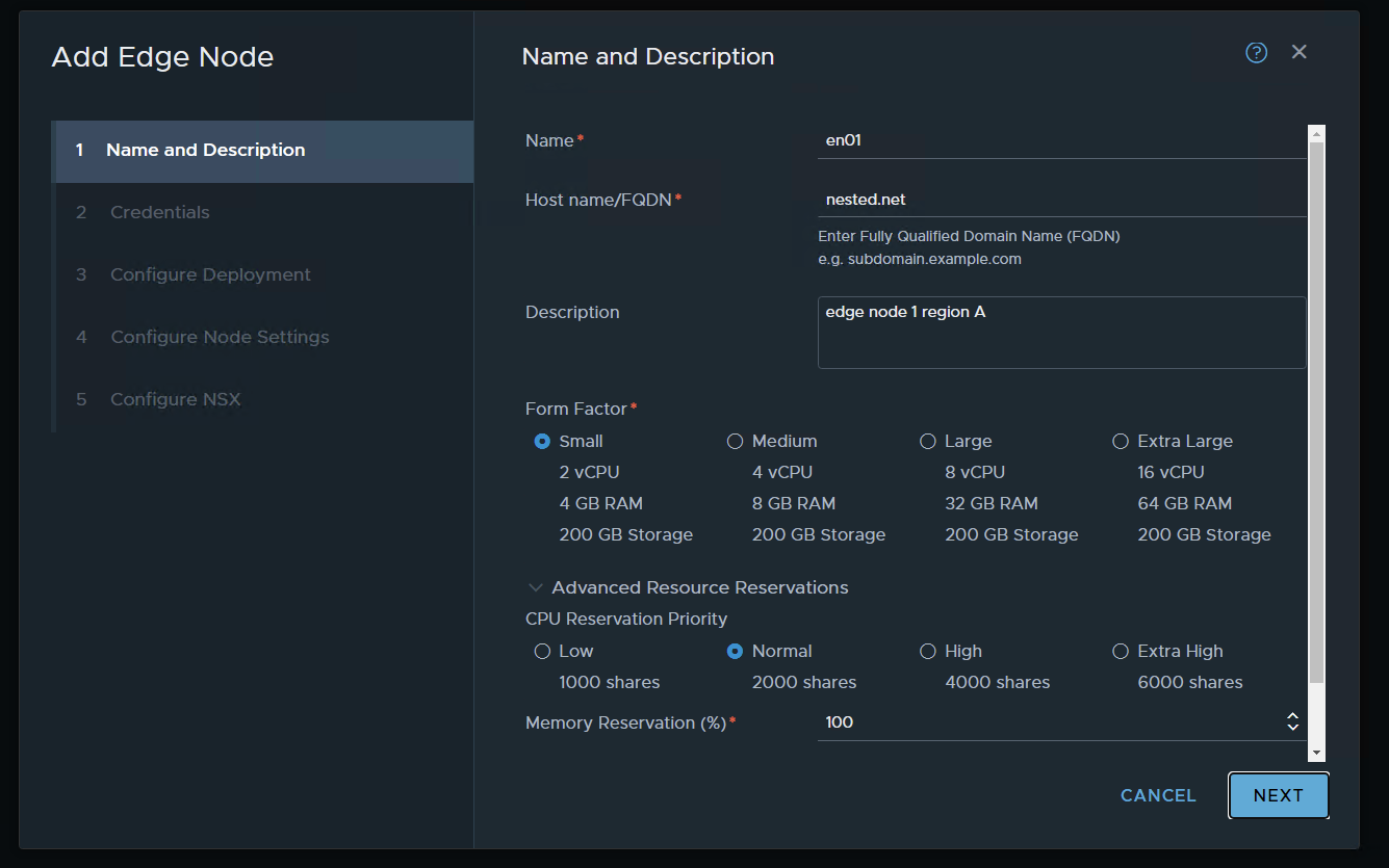
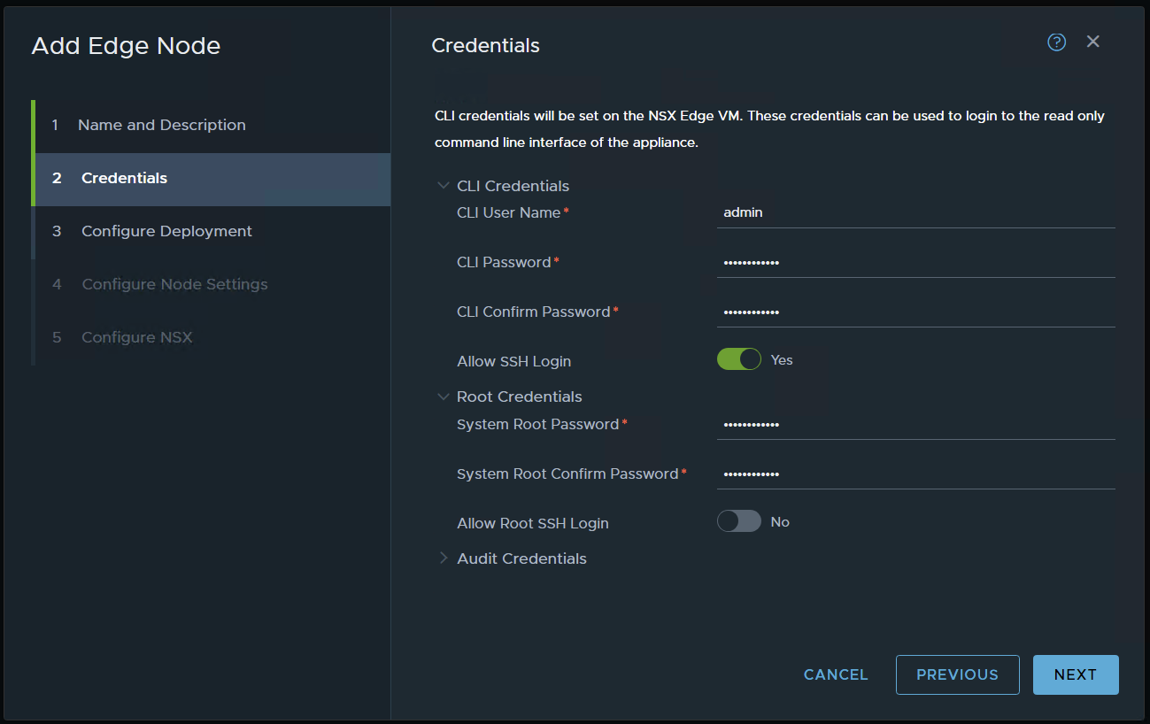
set credentials and NEXT / ALERT the above pic as a typo i didn’t typed just the domain i typed en01.nested.net
choose your settings and NEXT in my case, I’m using a resource pool to place the edges and also placing them in my nested VSAN.
I’m using static management IP’s
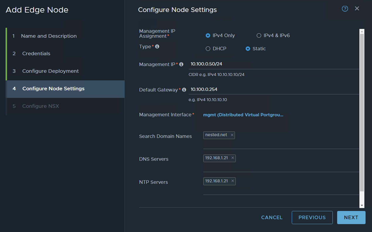
press on the management interface and choose your management port group
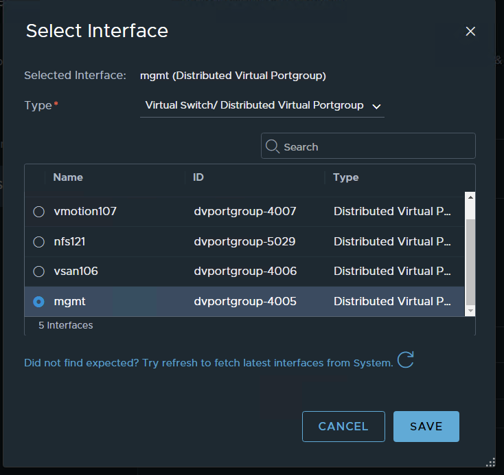
SAVE and NEXT
named the SW (not very important in this setup)
choose your transport zones: in my case two I have previously configured the VLAN and the Overlay TZ,
choose your edge node uplink profile
For TEP IP i will use the previously configured IP POOL
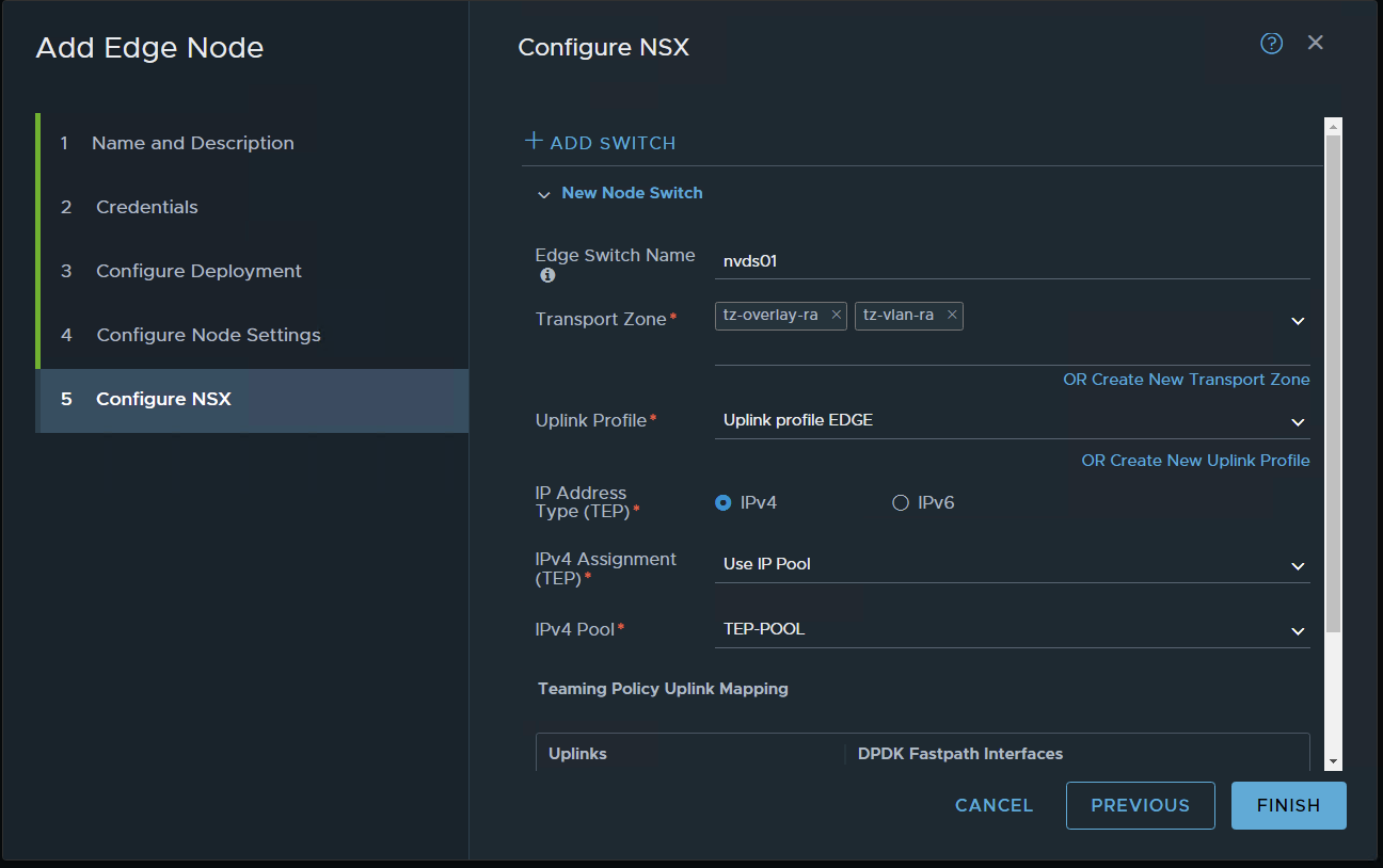
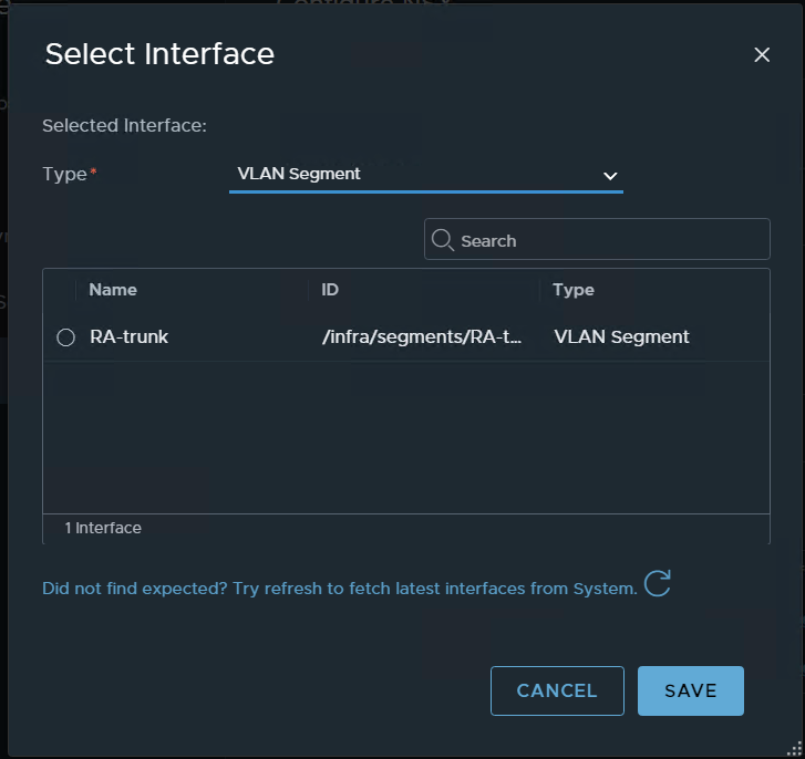
for the interface – choose the VLAN segment choose the segment we previously configured for vlan trunk
apply to the two interfaces
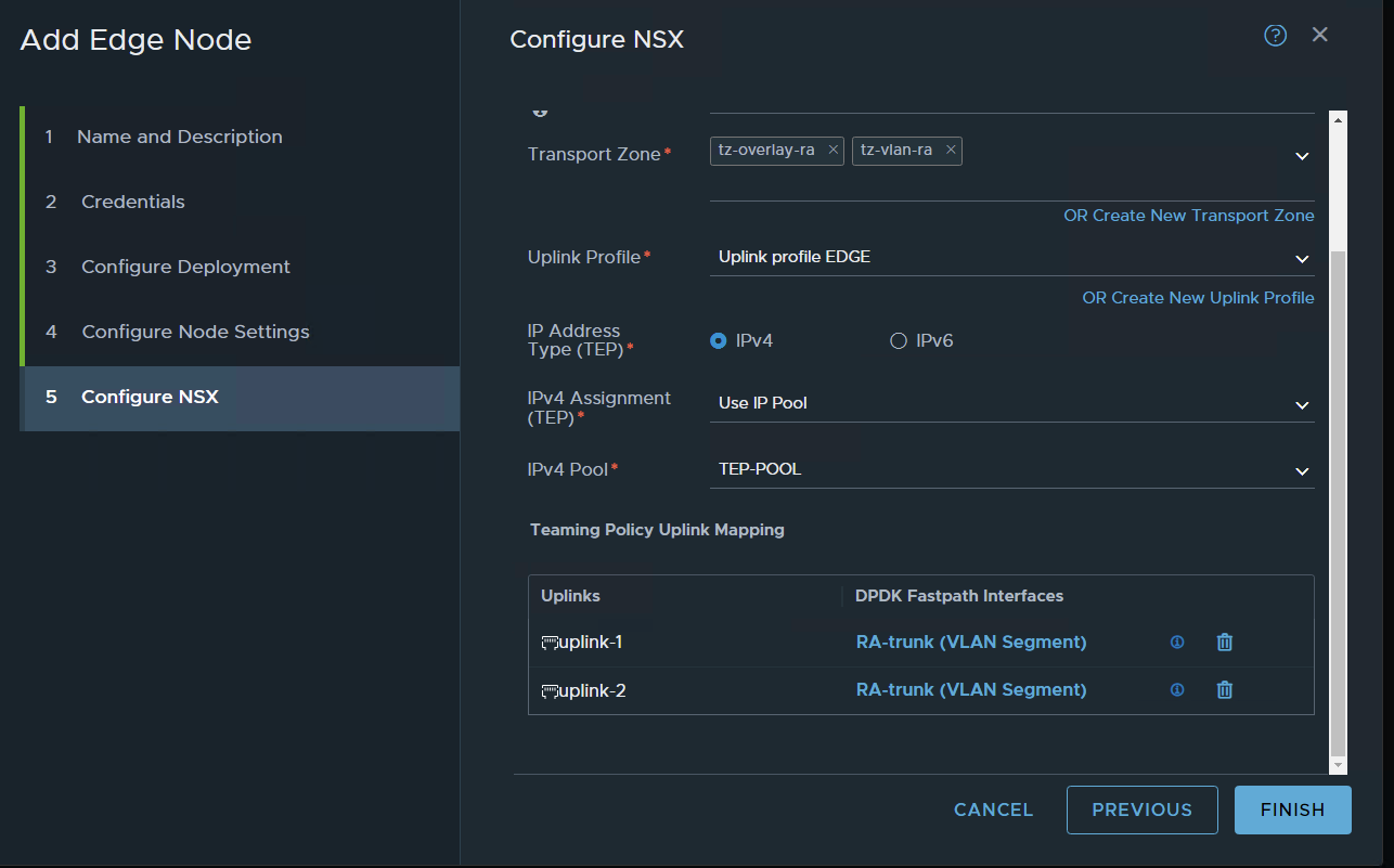
FINISH
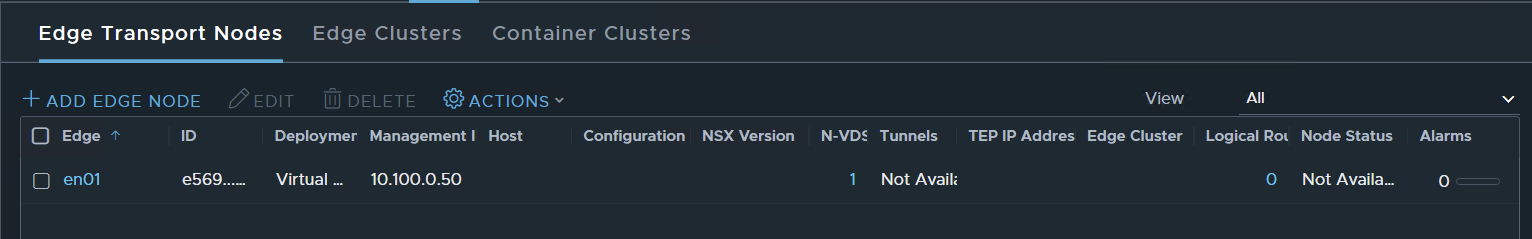
wait for deployment
Done
Now let’s set a second EN to create an Edge Cluster
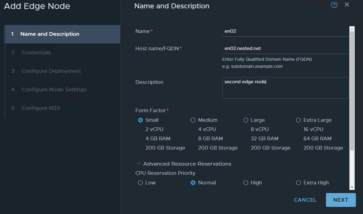
same stuff as for edge node 1
Keep in mind that on nested virtualization it takes a bit more time for things to happen so edge nodes take a bit more than usual to be at 100%
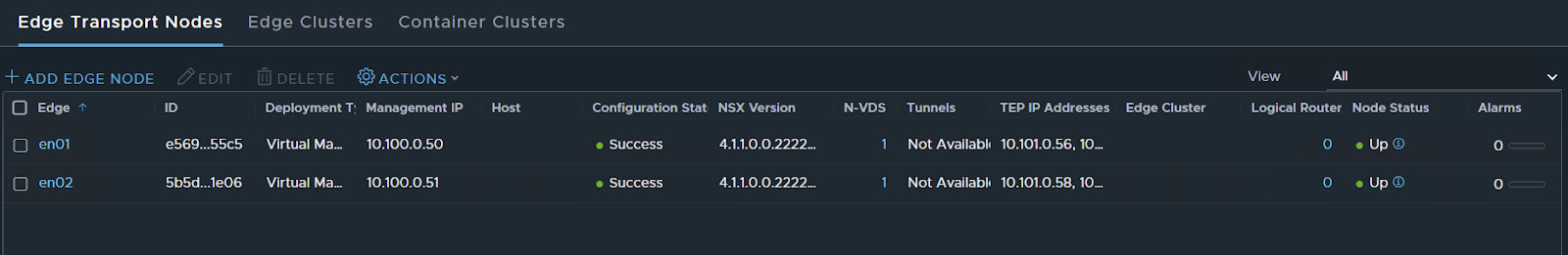
Ok now that I have the two nodes let’s create a cluster
the next TAB Edge Cluster press ADD EDGE CLUSTER
type the basic information
you will see on available the two nodes select them and pass them to the right side to Selected
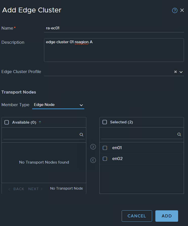
ADD

Now we need to create a segment
Networking/segments
This segment will be used by the T0 interfaces to reach outside. I have created a network 10.110.0.0/24 on VLAN 110 I will use this one for interconnecting with my VYOS router.
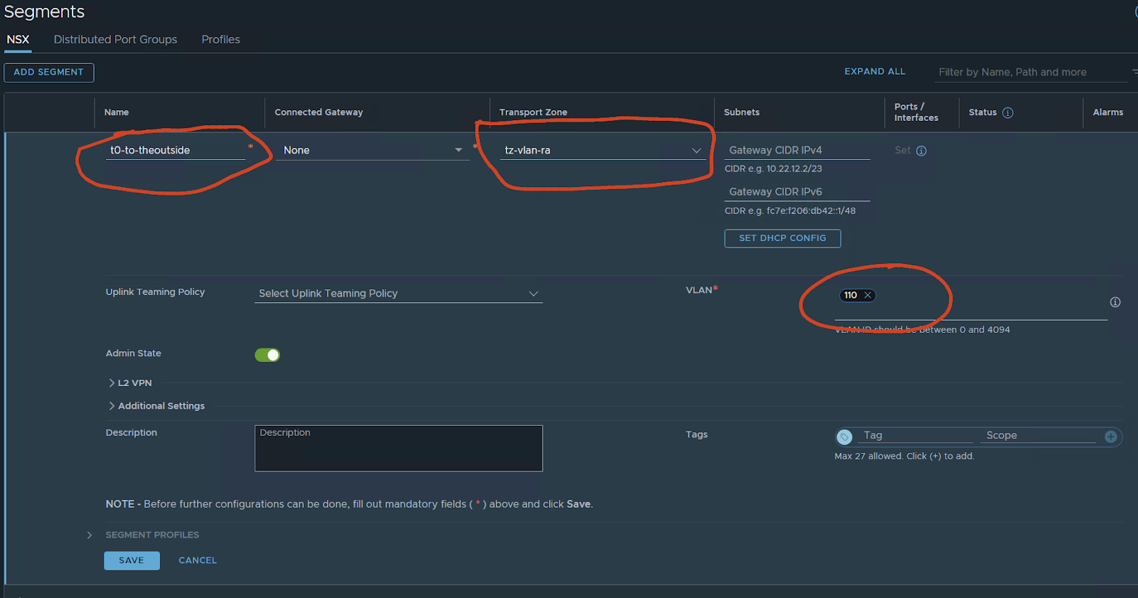
save

NO
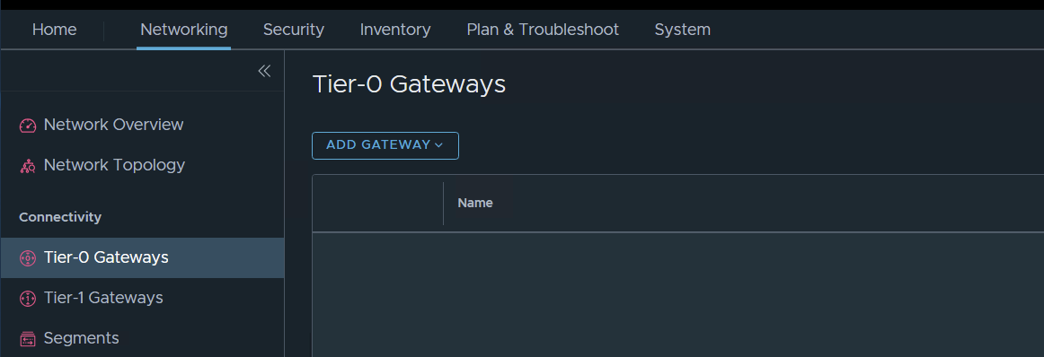
Now let’s create a T0 gateway
Networking / Tier-0 Gateways – ADD GATEWAY
in my case I want to test ACTIVE / ACTIVE stateful services i will choose this opinion
But T0 can be in A/S A/A and A/A with stateful services.
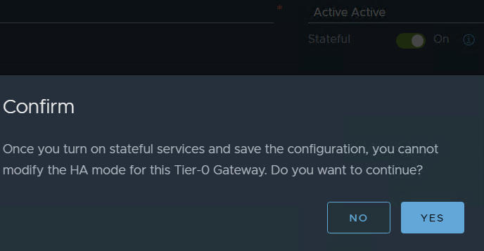
If you want to follow my guide do so but, like I said you can have A/S, A/A only stateless services, or A/A Stateful
In my case I want to have FW and NAT on my T0 and also have an Active / Active deployment in NSX 4.0.1 VMware made this possible I want to test it on my Lab.
Before 4.0.1 if you wanted to have NAT, FW, or any other service that was stateful you need to deploy in Active / Standby.
For more details check VMware documentation.
Configure a T0 in some cases might have many opinions in case will be simple but still with some configurations.
Edge cluster: your edge cluster
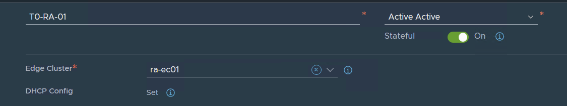
Press SAVE and continue with the configuration YES
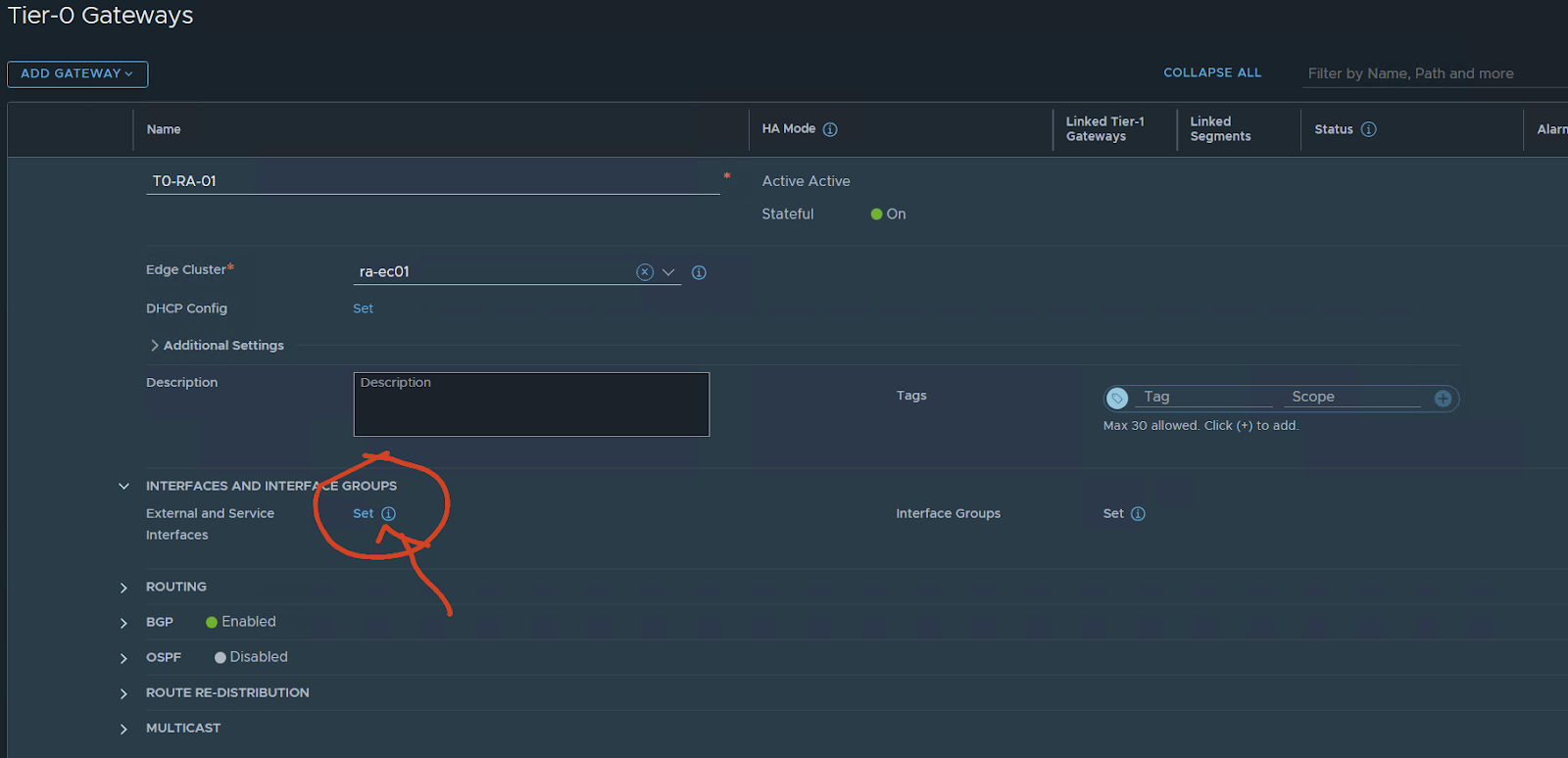
Interface and service groups press set
name of the uplink:
In my case, I only have one Vyos simulating a TOR switch/router connection.
I will have 1 interface for uplink per edge. if i wanted the test to be more real I would configure two vyos two VLANS and 4 interfaces configured two per edge node.
For only testing, I will have 1 per EN
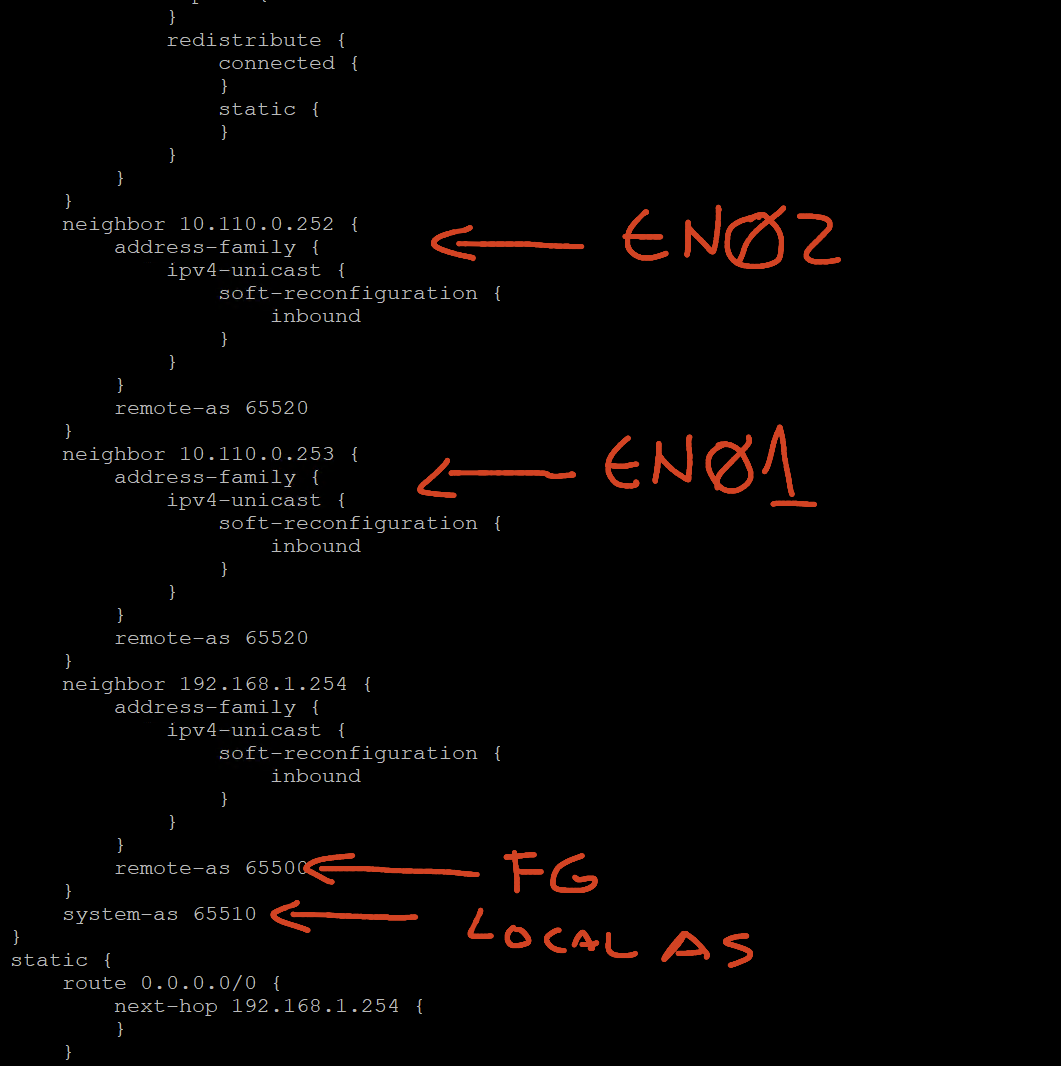
The EN01 will have ip 10.110.0.253 connected to the created segment using VLAN 110.
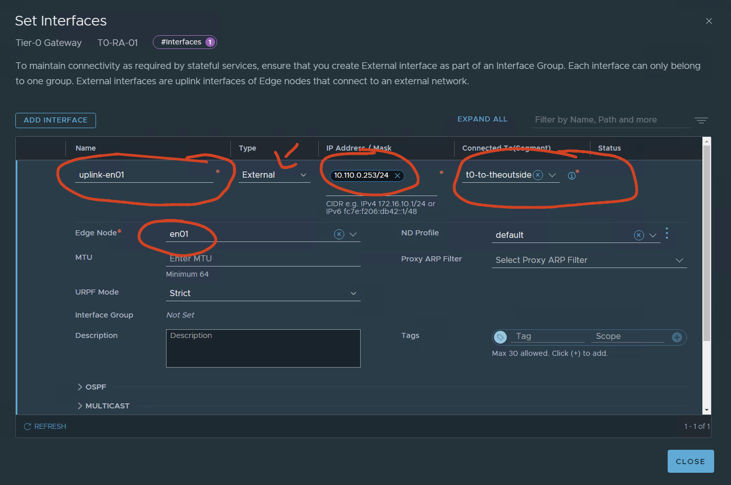
SAVE
Second uplink EN02
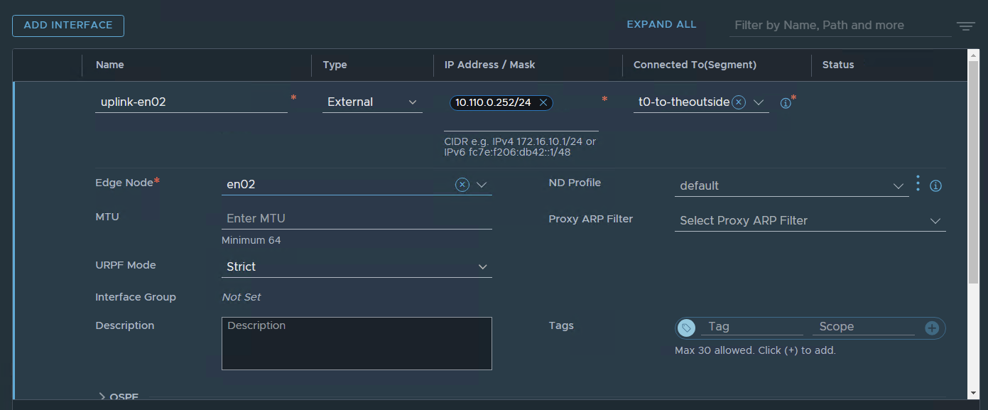
SAVE
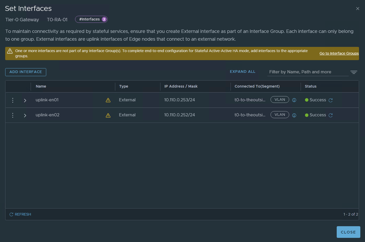
Since we are configuring A/A stateful we need to create and configure interface groups
Please note that in real-life implementations I would configure two uplinks per edge node as an example:
10.110.0.253 en01-uplink-1 10.111.0.253 en02-uplink-1 , 10.110.0.252 en01-uplink-2, 10.111.0.252 en02-uplink-2
let’s configure it:
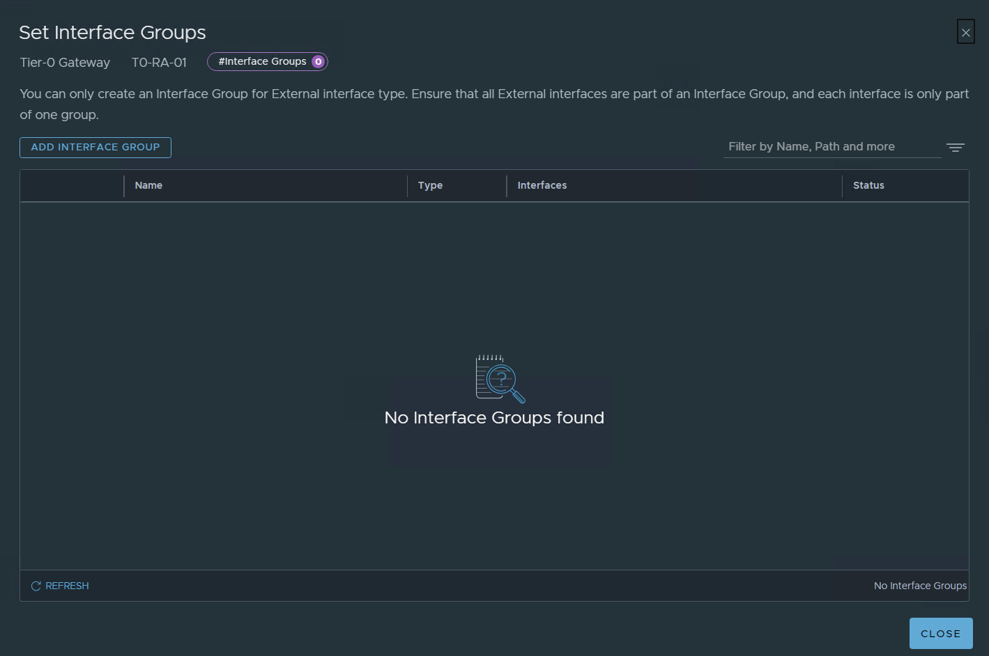
ADD INTERFACE GROUP
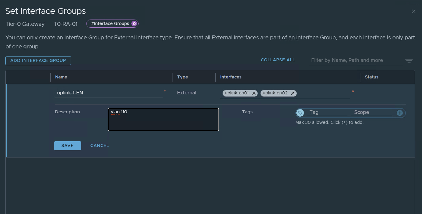
SAVE
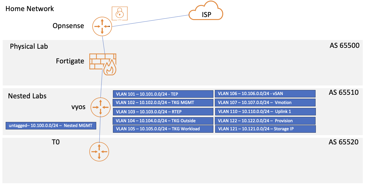
In my lab I have previously setup BGP between my FG and my Vyos In the lab I will use BGP in the T0.
If you don’t need Dynamic routing just configure a static route
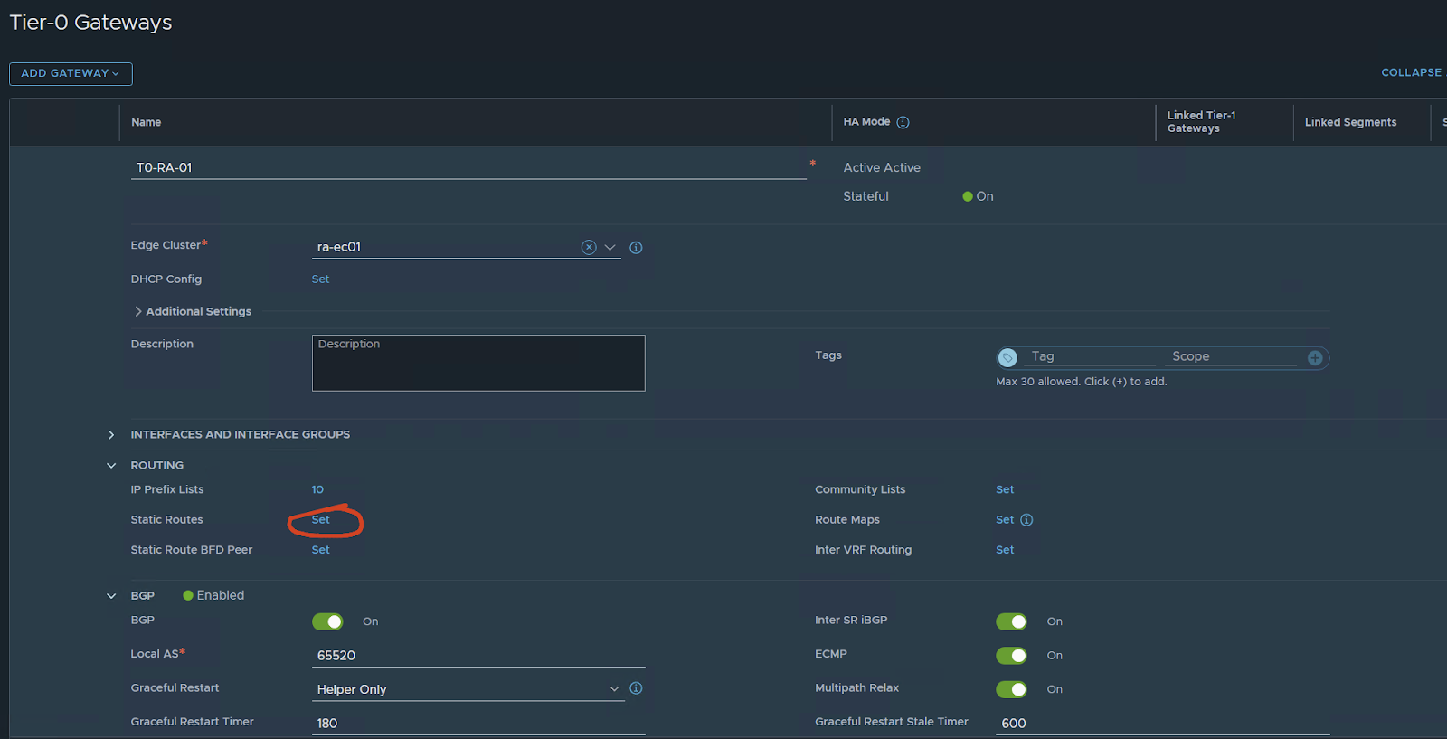
Now let’s configure BGP
First:
My nsx AS: 65520
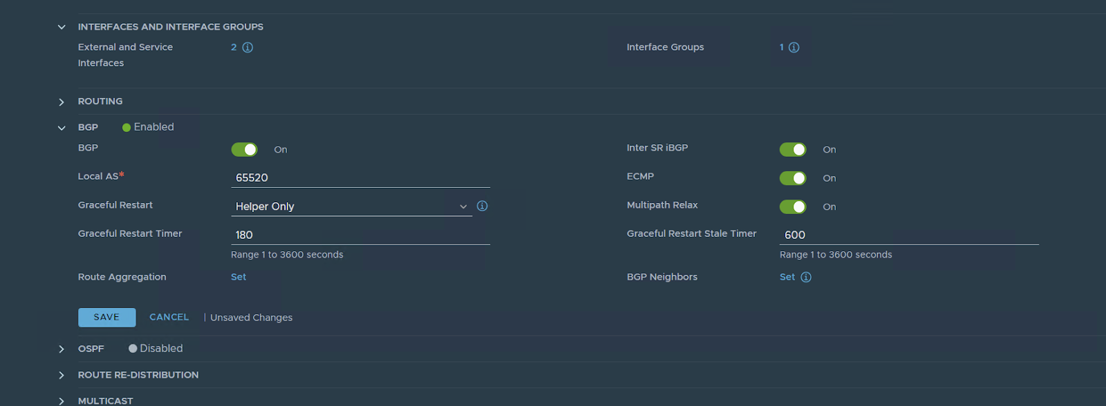
set the BGP neighbor config
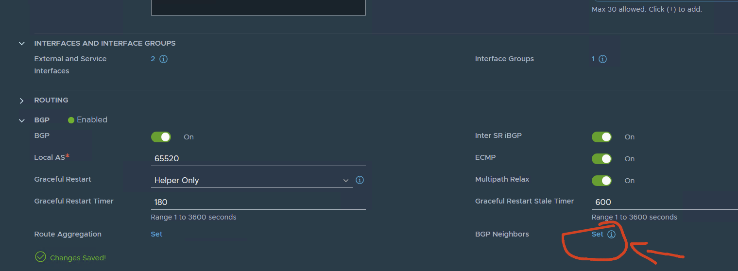
Notes: I have already my Vyos configured for BGP with the two ip addresses of EN01 and EN01.
In Another Post, I will show how to configure the vyos for the LAB with BGP
A simple layout of my lab, in another post I will explain in detail my lab setup.
Let’s go back to configure BGP
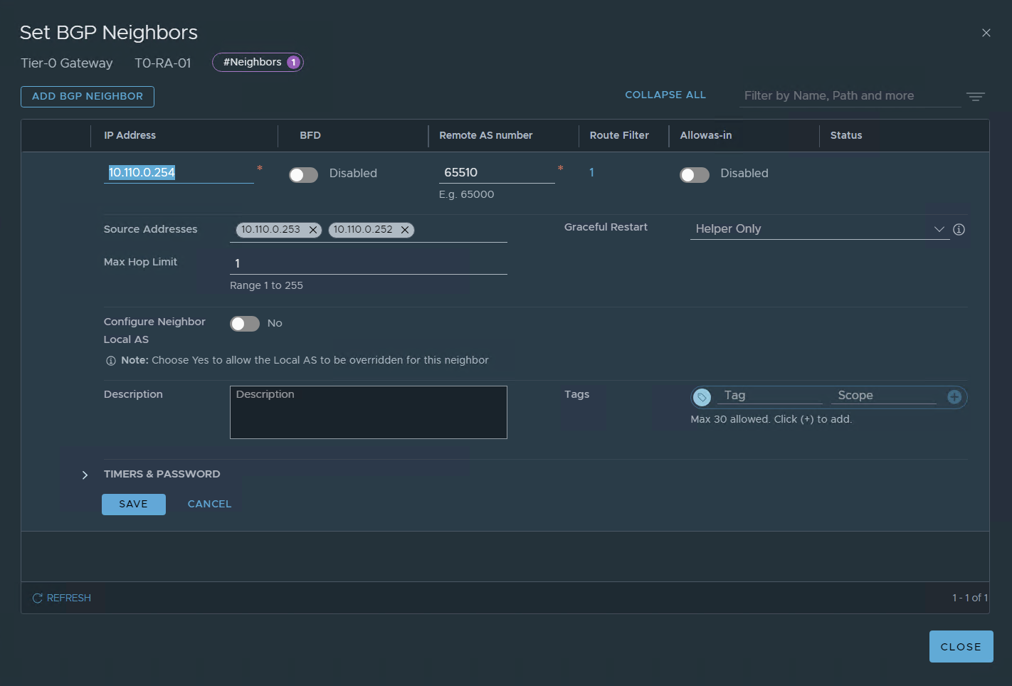
SAVE
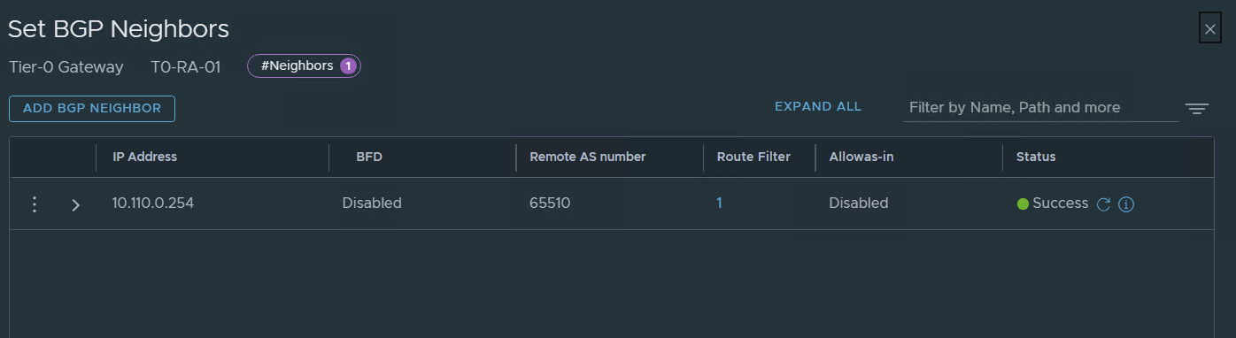
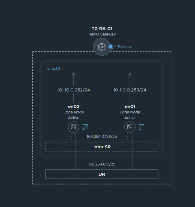
for now, we have this:
I Got this image from VMware Techzone:
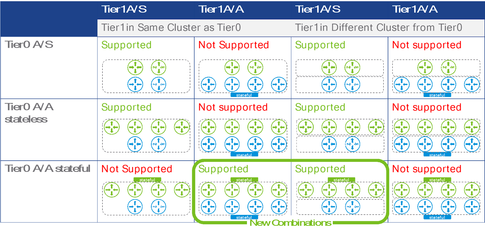
Since I only want to have a single edge node cluster in my lab I will setup the T1 as A/A
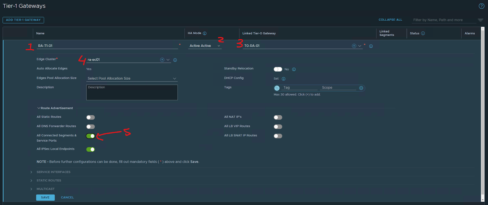
Now let’s configure a T1
1- name of the T1
2 – HA mode in my case A/A
3 – T0 Gateway to connect
4 – Edge Cluster
5 – advertisement
SAVE
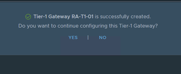
NO
Now let’s go back to
Networking/segments
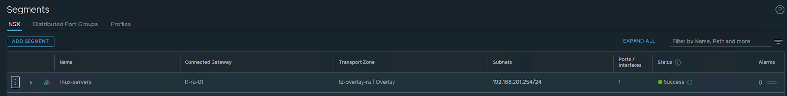
Create a new segment for my Linux VMS
save / no
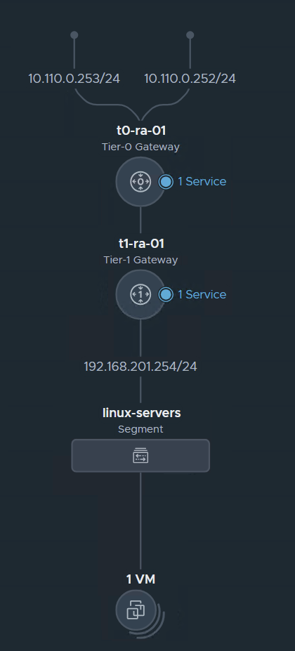
The segment VM is connected to my T1
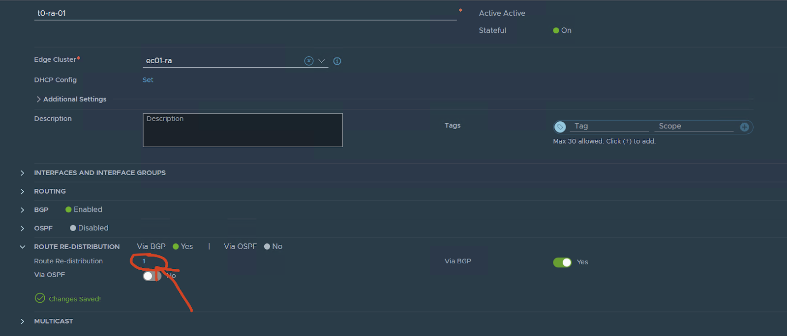
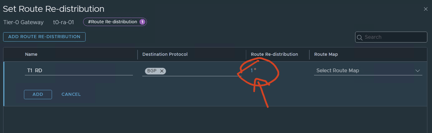
now go back to the T0
edit
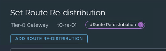
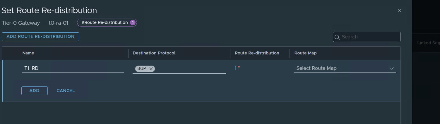
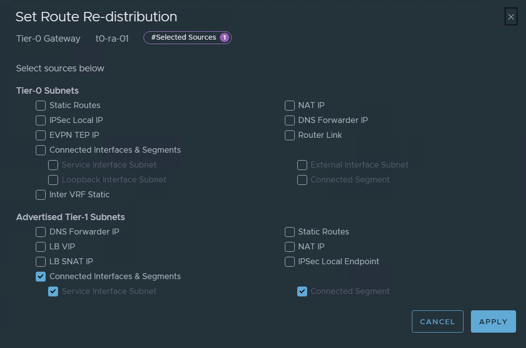
On route redistribution:
press and add
Now let’s check BGP and VM connectivity
On my lab VYOS :
show ip bgp 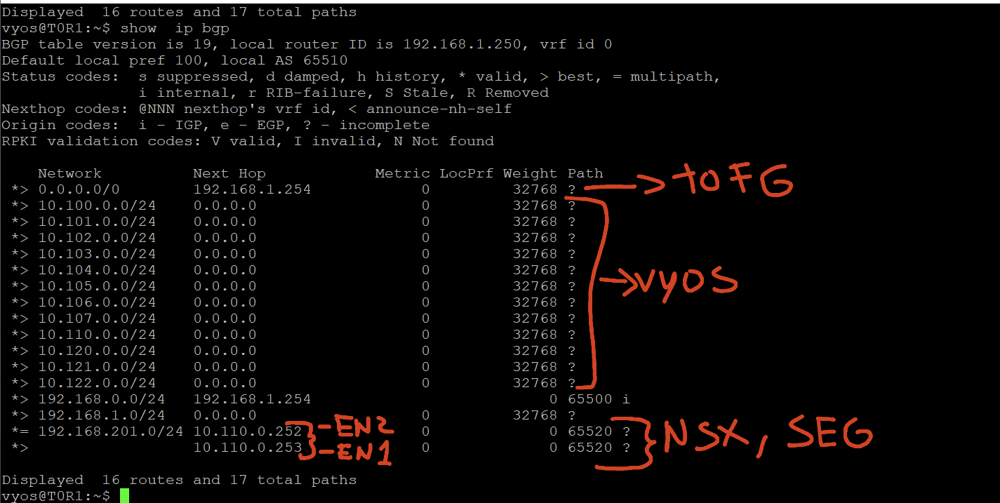
We can see the two interfaces of the edges nodes and the segment on the T1
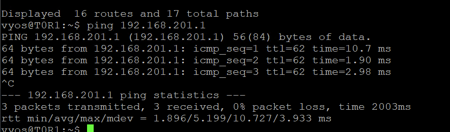
I can ping from the vyos my Linux VM on that segment
Now let’s check the Linux vm
I can reach my vyos outside the interface:
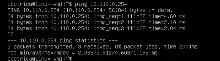
I have internet and DNS
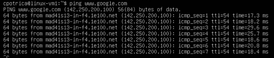
All looks good
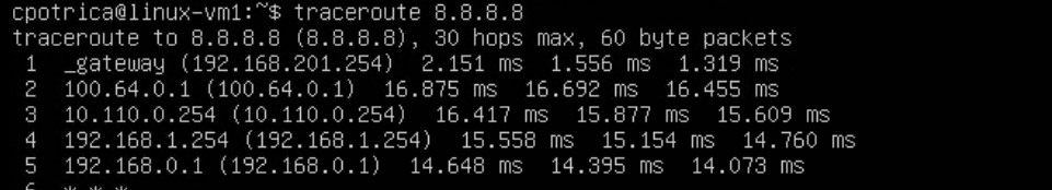
I reach the T1 , then goes to the T0 , then the vyos , FG , home router
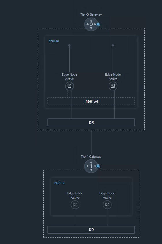
NSX Topology:
Fabric:
VM and fabric view:
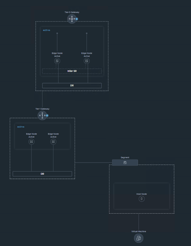
Recap We have configured NSX in terms of Networking with BGP, and also implemented the T0 and T1 in A/A stateful mode.
Also configured an overlay network for servers
Future Posts:
Security configuration with DFW and Gateway FW
NSX Advanced load balancer
Federation between Region A and Region B